

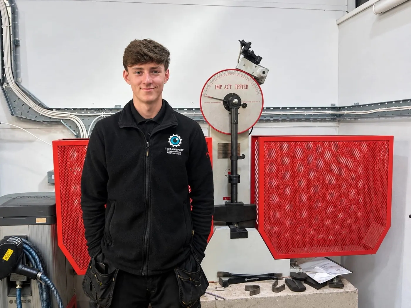
Charpy Impact Testing
Somewhere in your material specification there is a line reading something like 27 J at −20°C, average of three. It is easy to treat as a box to tick. It is actually the requirement standing between a structure that deforms when something goes wrong and one that breaks.
We carry out Charpy impact testing to 300 J in our Cumbria laboratory, including sub-zero conditioning, with specimens machined in house so notch geometry is controlled by the same quality system that reports the result.
Need charpy impact testing? Tell us what needs testing and where, and we'll come back with a price.
What the test measures
A standard specimen — 10 × 10 × 55 mm with a precisely machined V-notch — is struck by a swinging pendulum of known energy. Whatever the pendulum does not spend breaking the specimen carries it up the other side, and the height it reaches gives the energy absorbed, in joules.
That is not strength. A tensile test measures strength. Charpy measures toughness: how much energy the material absorbs before it fractures, and whether it tears or snaps.
The notch matters as much as the material. It concentrates stress at a defined point and forces fracture to start there, which is what makes results comparable between laboratories. A notch cut to the wrong radius, or fractionally off centre, produces a number that means nothing — which is why specimen preparation is a controlled process rather than a machining job.
Why the temperature is the whole point
Ferritic steels do not have one toughness value. They have a curve.
Above a certain temperature they absorb a lot of energy and fail in a ductile way — the specimen bends and tears, and the fracture face is dull and fibrous. Below it, the same steel absorbs very little and fails in a brittle way — almost no deformation, a bright crystalline face, and the crack runs.
The change happens across a surprisingly narrow band, called the ductile-to-brittle transition. Austenitic stainless steels and aluminium alloys barely show it; carbon and low-alloy steels emphatically do.
So your specification names a temperature because somebody worked out the lowest temperature the component will ever see — a January night, the outside of a cryogenic vessel, the seabed — and demanded evidence that the steel is still on the ductile side of its curve when it gets there. Get it wrong and the consequence is not a slightly weaker structure. It is one where a small flaw that would have been harmless propagates across the section.
Reading a result properly
A certificate reporting only absorbed energy tells you less than half of what the test produced.
- Absorbed energy — reported per specimen and averaged. Most specifications set a minimum average and a lower minimum for any individual specimen.
- Lateral expansion — how much the specimen spread sideways at the notch. A direct measure of ductility, and specified instead of energy in some pressure equipment codes.
- Percentage shear — the proportion of the fracture face that failed in a ductile manner, assessed against reference standards.
That last one carries the signal people miss. A result of 27 J at 80% shear and a result of 27 J at 10% shear are the same number describing two different materials: the first is comfortably ductile, the second is sitting on its transition and only just scraped the value. If you are reading joules alone, you cannot see how much margin you have.
Why three specimens
Charpy results scatter. Two specimens cut from adjacent positions in the same plate, tested at the same temperature, can differ widely — and near the transition they can differ enormously, because a small difference in local microstructure decides which side of the curve that specimen falls on.
That scatter is a property of the material, not a laboratory error. It is why every specification asks for three and judges the average, and why the individual minimum exists alongside it: results of 40, 40 and 5 J average 28 and would pass a 27 J average, while describing a material that failed catastrophically once in three attempts.
Where the specimen comes from
Orientation. Rolled plate is not the same material in every direction. Specimens taken transverse to the rolling direction routinely give lower toughness than longitudinal ones, because elongated inclusions from rolling line up to help a crack across the plate. Your specification states the orientation, and it should match the direction a crack would actually run in service.
Location. For weld procedure qualification, specimens come from defined positions: weld centreline, fusion line, and set distances into the heat-affected zone. Those positions exist because the HAZ is where toughness is most likely to have been damaged by the welding thermal cycle. Testing weld metal alone and calling the procedure qualified misses the region most likely to fail.
When a set fails
Most standards allow a retest under defined conditions — typically where the average passes but one specimen falls below the individual minimum, or the average falls slightly short. That normally means three more specimens, all of which must meet the requirement. What standards do not allow is repeated retesting until a set passes; that will not survive an audit.
Before retesting, it is worth asking what actually failed:
- Was the material right? A grade substitution shows up here first, and positive material identification is quicker than a retest.
- Was the heat treatment right? Normalising and post-weld heat treatment both change toughness substantially.
- Was heat input controlled? Excessive heat input coarsens the grain structure in the heat-affected zone, and coarse grains are less tough — one of the main reasons WPSs cap it.
- Was the specimen prepared correctly? Notch geometry, orientation and location are all candidates before concluding the steel is at fault.
A failure is information. Treating it only as an obstacle to a retest wastes it. Where a set fails we will tell you what the fracture faces suggest before you commission more specimens — metallographic examination of a failed specimen frequently identifies the cause in a day, which is usually cheaper than three more specimens and a second failure.
What we report
Absorbed energy per specimen and averaged, lateral expansion, and percentage shear, with specimen orientation and location stated — because a certificate omitting those is not traceable to anything.
Impact testing sits alongside tensile, hardness, bend and fracture testing in the same laboratory, which matters for procedure qualification where all of them feed one WPQR. One provider, one set of records, one certificate.
If you have coupons that need testing, or a specification you are not sure how to sample against, send us the drawing and the material grade and we will tell you what the test programme should be.
Destructive
Testimonials
“Test Inspect is our go-to company for non-destructive testing and welding inspection. We use them almost on a weekly basis for magnetic particle and visual on our Sellafield projects where a great deal of oversight is placed on the NDT and the quality of our welding and fabrication.”
Richard Tubman -Numech Managing Director
“My dealings with Test Inspect have been extremely easy due to their professional proactive working ethics. The service was very efficient and all of my expectations were met. I chose Test Inspect to carry out the works on my project as I have worked with Lee for many years and know that he and his team will always provide exactly what I require and to the highest standard. I would certainly recommend others utilising Test Inspect services.”
Callum Woodend WCELOperations Director
“Cheers Tony, and thanks again for your help. Great turnaround and service from Test Inspect,
John IrvingMechanical Quality Inspector
Service Delivered - Sellafield Welder Qualification,
Turnaround Time - <24hrs”
“Firstly I'd like to thank you both for your contribution to the last phase of work for RR SMR to help identify the benefits of digital image capture with gamma sources and the potential for reducing the working space envelope. Your assistance and expert knowledge was very much appreciated.
Doug WylieTWI Ltd
Service Delivered - Level 3 Radiography and Digital Radiography R&D”
